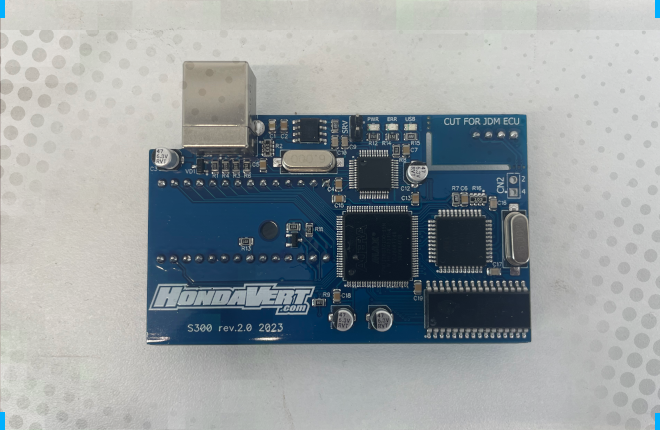
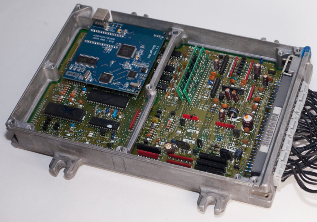
HondaVert S300 daughterboard for OBD1 ECU, which significantly expands capacity of it. Datalog, RealTime Programming, Lunch Control, Boost control, Nitrous control, ITB and more. Fully retains all vehicle systems. ABS, Gauges, Air conditioner and etc.
HondaVert S300 compatible with the following cars
- 1992-2000 Integra DA/DB/DC
- 1988-2000 Civic EF/EG/EH/EJ/EK/MA/MB
- 1992-2000 Domani
- 1992-2001 Prelude IV/V Gen
- 1993-2001 Accord V/VI Gen CC/CD/CE/CF/CG/CH
- 1998-2001 Torneo
And many other cars with 4-cylinder B / D / F / H series engines
*On some vehicles, it is additionally necessary to install the “correct” ECU and wire jumper harness.
What sotware can I use?
- Hondata SManager
- Honda Tuning Suite (HTS)
- BMTune
- CROME
- TunerPro RT
- TurboEdit Pro
- Many other softwares compatible with OSTRICH 2.0 protocol

All Hondavert S300 board versions compatible with SManager 2.2.8. Also S300 board version 1.6 and more moderm also works perfectly with SManager 2.7.5.
Non recommended software used for tuning can damage your engine.
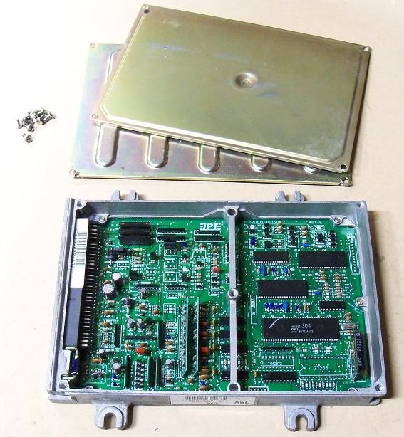
HondaVert S300 can be installed to OBD1 ECU

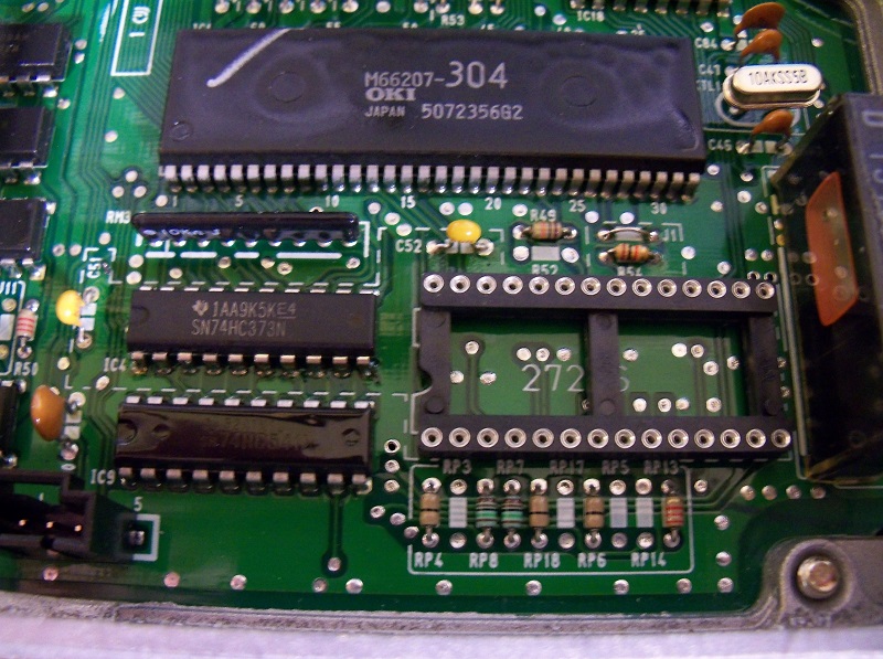
HondaVert S300 USDM board installation
To install the board you need some tools and parts:
- Soldering station and soldering iron
- OBD1 ECU and S300 USDM board
- S300 installation kit (come with the original product)
- DIP28 PIN Connector – 1pcs
- 5PIN Connector – 1pcs
- Resistor 1 kOhm – 1pcs
- Jumper- 1pcs
- Capacitors 0,1 mF – 2pcs
- Latch register 74HC373 – 1pcs
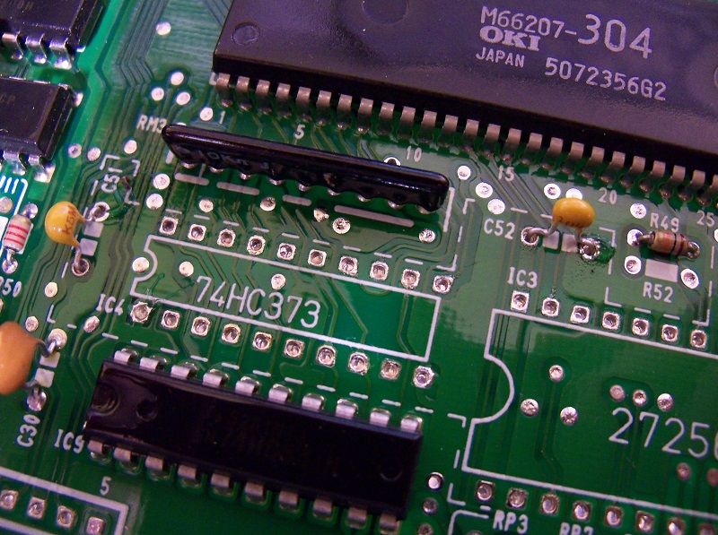
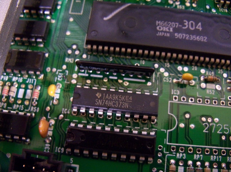
CHECK YOURSELF: The notch on the chip must correspond to the notch on the
board drawing
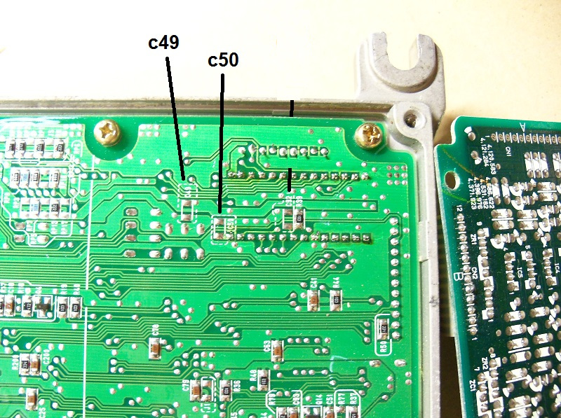
HondaVert S300 JDM board installation
To install the board you need some tools and parts:
- Soldering station and soldering iron
- OBD1 ECU and S300 JDM board
- S300 installation kit (come with the original product)
- DIP28 PIN Connector – 1pcs
- 5PIN Connector – 1pcs
- Capacitors SMD – 2pcs
- Latch register SMD 74HC373 – 1pcs

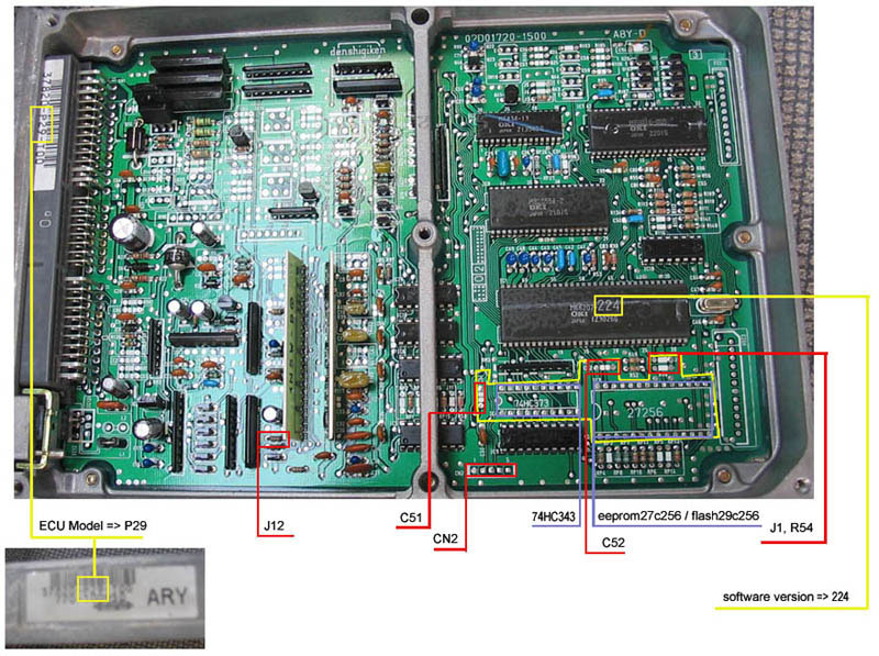
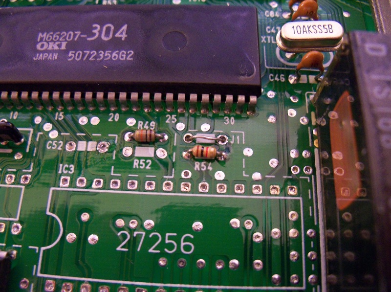
We need to modify seven components: C49, C50, J1, J4, CN2, 74HC373, 27256


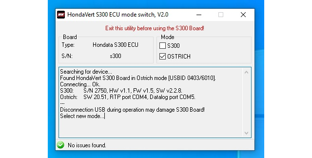
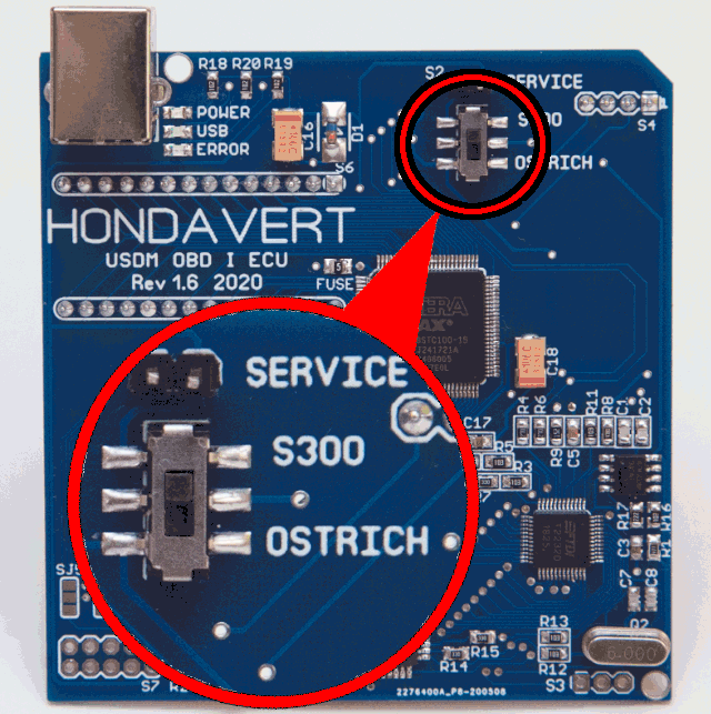
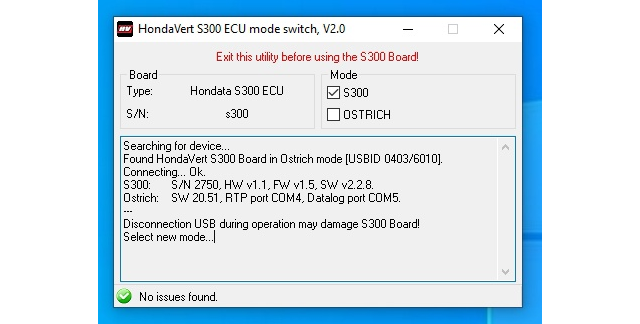
Switch S300 or OSTRICH mode

Emulator memory will be cleared when you change board mode
Set OSTRICH mode (HTS, ecTune, BMTune, CROME etc)

Set S300 mode (Hondata SManager)
How to run automatic gearbox with Hondata SManager
This instruction was released thanks to the guy with nickname Buka55ru, who many years has been successfully using HondaVert for tuning his car with automatic transmission
ECU Hardware and Wiring
To work, we need the following OBD1 ECU output:
A17 IAB — Secondary Intake Runner / A/T Lock-Up Solenoid
Manual ECU. This type of ECU needs to be modified by adding the power output A17 from the ECU, to run automatic valve control. Read below.
Automatic ECU. This type of ECU already has everything you need from the factory, does not require any modification.
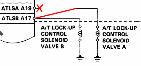
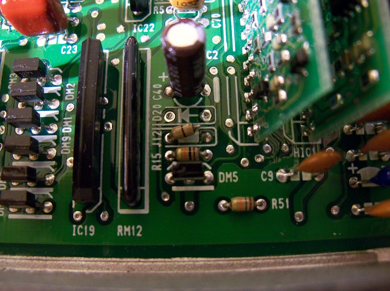
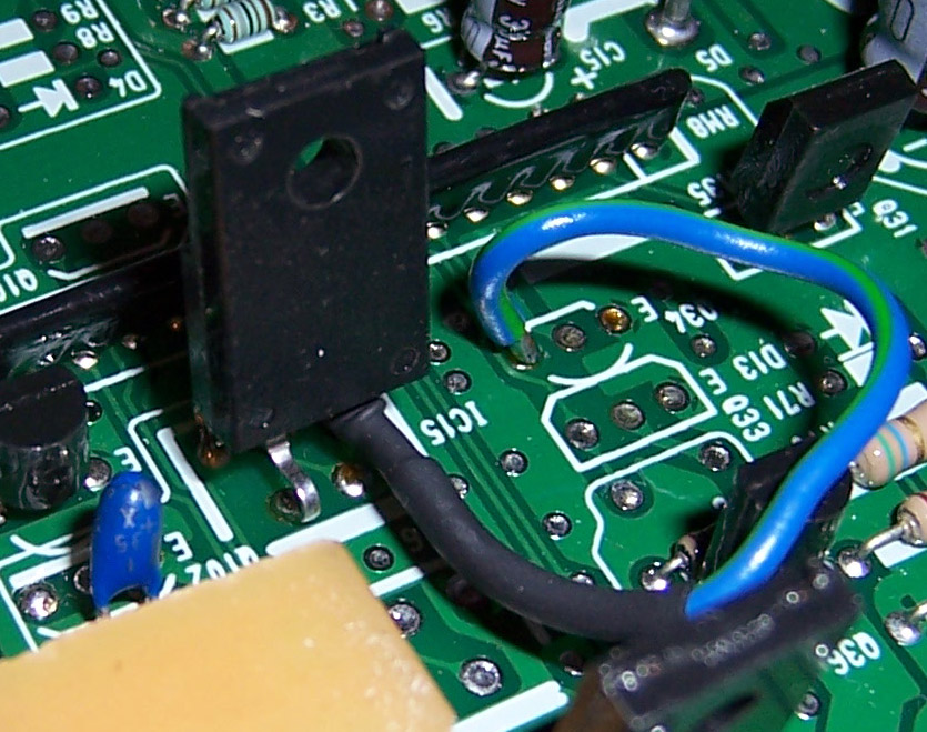
A17 IAB Modification (for Manual ECU)

IC16 5050S High Side Swith
R68 820 Ohm Resistor
D13 4001 Diode
C78, C79, C91 22 pF Capacitors (sometimes soldered from the factory)
SManager ECU calibration
To run with automatic transmission, we will use a great feature available in SManager – programmable events.
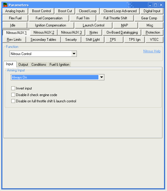
Go to the Nitrous/AUX 1 event and configure the following parameters:
Function —> Nitrous control
Input tab —> Always on
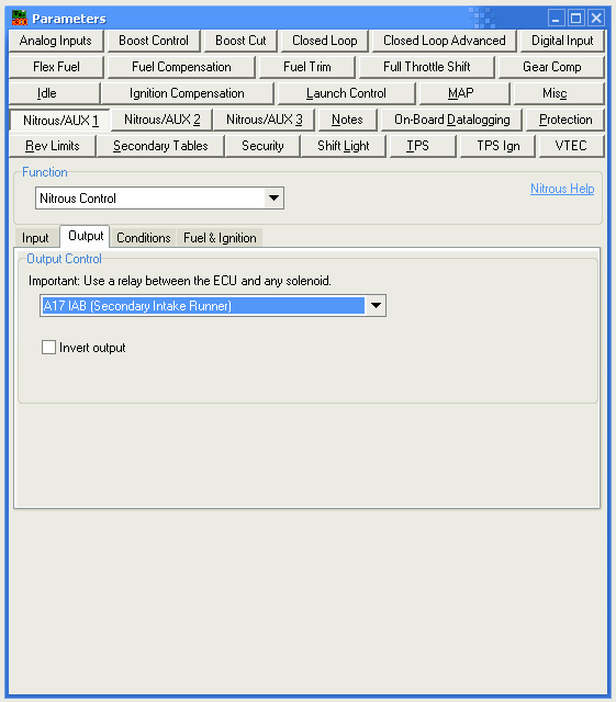
Output tab —> A17 IAB (Secondary Intake Runner)
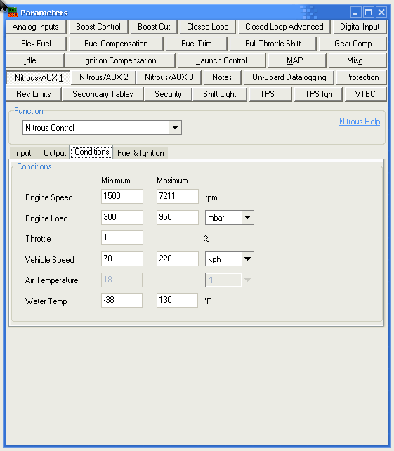
Conditions tab
-Engine speed —> 1500-7200 rpm
switching on early so that there is a margin to failure when locking
-Engine load —> 300-950 mbar
950 is 8.5 column, if less then flying off when cruising on 100 kmh
-Throttle —> 1%
-Vehicle speed —> 70-220 kph
-Air Temperature —> -30 C
-Water Temp —> -37 – 130 C
Upload calibration to ECU and Go Driving 😉